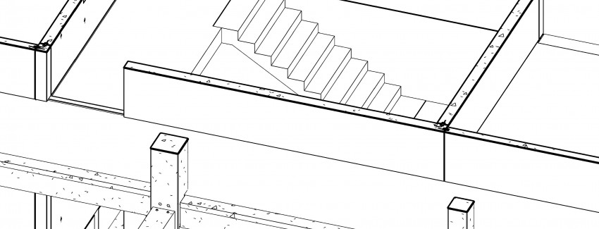
BIM (Building Information Modeling) is an intelligent 3D model-based process that gives architecture, engineering, and construction (AEC) professionals the insight and tools to more efficiently plan, design, construct, and manage buildings and infrastructure
Building Information Modelling (BIM) is about everyone understanding a building through the use of a digital model. The digital model holds all the information that construction professionals need to design, construct and maintain that building. The information within the digital model grows with an increasing level of detail so that it reflects the building as it is built and then ultimately as it is used. BIM is the future of the construction industry.
Currently Prefabricators includes steel and precast concrete updates their design flow to include BIM widely on their design process to facilitate issuance of fabrication drawings, coordination as the most issue in the precast concrete production that saves time and effort doing early coordination when all project team understands the flow, connection design and how the precast elements looks like.
Furthermore, prefabricators monitor the elements from design to erection to ensure the best of information flow between departments, decision can be taken on the panel knowing its status.
The key of the whole precast concrete process is delivering the information needed to production ensuring no further changes will happen to the elements that been sent to production in order not to change the mold or rework on the same element, whatever method it is the answer is always how the information is gathered in one place and how the flow to site is made easy, the models should enable element and accessory lists and data transfer directly from the model, and at the construction stage support site management.
BIM models can be developed at early stages during bidding for precast concrete projects to estimate the quantities, visualize the building, early planning for elements numbers that will be casted to ensure that is included into a precast concrete offer to the owner.
Once the project is in hand, the precast concrete fabricator can use the same model to add the final design and details into the same model and use the same model for coordination between Arch. And MEP, that is a level of LOD300 model in precast as previously defined coordinated erection drawings, the same model is then to be used for further estimation of the designed concrete quantities that been used in bidding by the company.
If any changes happened during the design stage, the information directly is known that there is a change and prefabricator may need to take a decision about the project if the changes is big, that early notifications happens to save tons of claims and waste of time later on project compilation when a prefabricator closes out the as built and check final quantities.
Design teams uses the model to Map the bar code for each element inside the model, where the shop drawings generated, its matter of choice whether the fabricator wants to produce the shop drawings at LOD 400 to include the reinforcement detailing inside the model along with bar bending schedules or not.
Summary on Precast concrete process
In a perfect condition, BIM are developed by the architects and MEP are using BIM as well, this is currently not always the case, Precast concrete fabricators might be the only one in the process who is using BIM for his own benefits. The problems happen then with coordination with other disciplines who uses CAD instead of BIM.
The precast concrete fabricators are enforced by then to import the most important structural openings from CAD coordinated drawings that is received from MEP, knowing that precast design team has to extract all the drawings in 2D format to the MEP.
Once the MEP openings are added in the model again, the precast design team can now generate the shop drawings include the final structural openings to production, with another 2D MEP set of drawings to include sockets, pipes and other MEP items inside the panel, both drawings are used together to produce the panel, that makes it a difficult process.
Comments (1)